*breaks out graphics editor*
Use a "low pass filter block" with the resulting decimation, the sampling rate set to the rate coming into the filter, and the cutoff frequency let's say to (15.0/16.0 * 2e3) which allows for a transition width of (1.0/8.0*2e3).
I would really like to understand where are these coefficients coming from? I have set them to the value you suggested and I could not get it to work. Is the 1/8.0 because i am using 8 samples per symbol ?
So here's your 200kHz of bandwidth that you know get from the USRP:
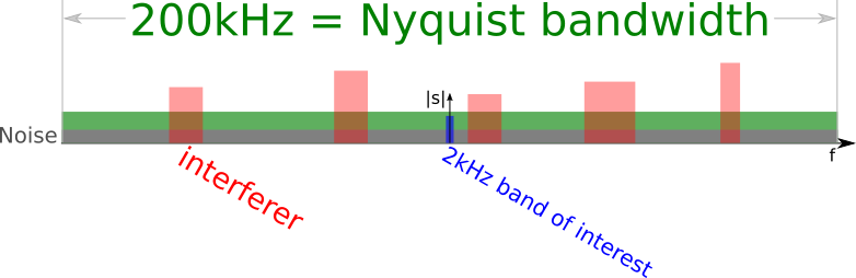
Obviously, you want to get rid of 198kHz of those 200kHz! Now, I'm assuming that your actual signal "fits" inside the 2kHz, i.e. has a bandwidth <2kHz.
Let's focus on what we care for:
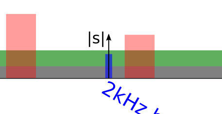
Hm, how does one go about getting a 2kHz signal out of a 200kHz signal?
The answer is surprisingly simple: You just throw away 99 of 100 samples!
Obviously, it's not that simple, though. Because if we do that, we'd get 99 aliases in addition to our 1 wanted signal in the resulting 2kS/s stream. Hence, we first need to filter out everything we don't want.
Ideally, we'd need a filter that really doesn't touch anything with |f| <= 1kHz and removes everything with |f| > 1kHz. Such a filter, however, is not mathematically possible¹.
With filters that inherently have what we call a transition zone, width, or region, we've got to make a compromise between
- letting a little bit of adjacent signal into our signal, and
- cutting away signal we might want.
A little graphic might explain that better:
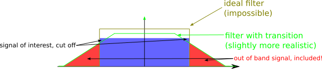
I think the point is clear: the less of interesting signal I cut off, the more out-of-band signal I keep.
What happens now with that:
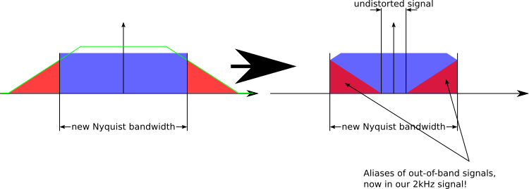
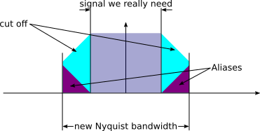
Two observations:
- Obviously, this filter is bad; its transition width is far too large
- If we know how much of the new Nyquist bandwidth we really
need, we can design a filter that has a transition width that
exactly spans twice the bandwidth from the upper edge of the
really needed signal to the upper edge of the Nyquist band,
because, assuming our filter is symmetrical, the alias of the
unwanted signal above will "land" exactly in the region between
the lower edge of the Nyquist bandwidth and the lower edge of
the really needed signal:
And that's exactly what I recommended. I assumed you needed
 of your new Nyquist bandwidth, meaning that at each edge you had
  of
that to spare for cut off/aliases, meaning that you can have a
transition width of
of
that to spare for cut off/aliases, meaning that you can have a
transition width of  of your bandwidth.
Best regards,
Marcus
¹ it is, it would just be infinitely long, so it's not useful to us mere mortals.
The placement of the decimation depends a bit on your actual signal of interest; generally, the earlier, the better, since that simply eliminates a majority of noise power.I have kept the LPF with above coefficients right after the USRP block and before the FLL band edge filter.Make sure, however, that the passband width of the filter is "wide" enough so that the FLL can still work.
The only parameter to LPF wrt BW is 200kHz (which i assume is passband width you referred to), else the transition width is descried as above. Not sure what limits does FLL work with well to say 200 KHz is fine.
I am following the code from the generic_mod_demod.py class in gr-digital/python/digital/ folder, and I see the RRC filter doesn't use a sample_rate in RRC filter and instead use a pfb_arbitrary_resampler with just the "samples_per_symbol" as input.So I am not sure where the information of sample_rate=2kHz is used.
I am not clear what the FIR Interpolator Taps should be for oversampling from 2kHz to 200 KHz and I am using RRC ones. But the resultant waveform is changed. Please see the grc attached, I would be grateful to you if I could get clarity on it.
Thanks,AbhinavBest regards,
Marcus
On 21.10.2015 22:45, abhinav narain wrote:
Hi Marcus,I see your point, and I can add intepolation factor as 196K/2K =98 in my transmitter.
Can you please tell me about what should I do in my receiver now that I have to do decimation.I have the exact grc file attached.I am doing :USRP Source-> FLL Band Edge-> Polyphase Clock Sync with RRC RX filter [{ firdes.root_raised_cosine(ntaps,samp_rate,sps, rolloff, int(11*sps*ntaps)) }corresponding to tx filter of {firdes.root_raised_cosine(ntaps, samp_rate, sps, rolloff, int(11*sps*ntaps))} ]-> Costas Loop -> MultiplyConst->Constellation Receiver ...
I do have to place a decimation filter I suppose with factor 196/2 (= same as in interpolator filter), but the polyphase Sync block doesn't have a Decimation factor in it.
In case I place Decimation block before FLL BandEdge block, I need to have tap coefficient and I am not sure what should they be ?I don't know how i can calculate square root of RRC taps and place those taps in both - Decimation block and Polyphase block.
Please suggest.
Thanks,Abhinav
On Wed, Oct 21, 2015 at 11:51 AM, Marcus Müller <address@hidden> wrote:
Hi Abhinav,
I think most of your questions have been answered in my reply to your reply to Sylvain's mail; basically, yes, you need to use a sampling rate >=196kHz, but no one is stopping you from putting any signal into that sampling rate that has a smaller bandwidth. See my comments on oversampling.
Best regards,
Marcus
On 10/21/2015 08:37 PM, abhinav narain wrote:
Hi Marcus,
On Wed, Oct 21, 2015 at 3:18 AM, Marcus Müller <address@hidden> wrote:
Hi Abhinav,
which USRP are you using?USRP N210I'm pretty sure none of our devices supports a 2kS/s sampling rate -- it's just far too low to get directly interpolated to a "usable" DAC/ADC rate. Especially those USRPs that can be equipped with RF frontends (daughterboards) that can operate at near-baseband (400kHz) shouldn't be able to work at such low rates. So: which daughterboard are you using?
I see your point, I am using Basic TX/RX daughterboard.I didn't notice the shell output but it makes sense now :
Terminal output:The hardware does not support the requested TX sample rate:Target sample rate: 0.001000 MSpsActual sample rate: 0.195312 MSps-- Tune Request: 0.400000 MHz-- The RF LO does not support the requested frequency:-- Requested LO Frequency: 0.400000 MHz-- RF LO Result: 0.000000 MHz-- Attempted to use the DSP to reach the requested frequency:-- Desired DSP Frequency: 0.400000 MHz-- DSP Result: 0.400000 MHz-- Successfully tuned to 0.400000 MHz
Basically, the minimum sampling rate is 196 Ksamples/sec
Hence, UHD should have told you that you can't use that sampling rate, and a higher sampling rate was automatically selected, inherently frequency-"stretching" the signal by the ratio of (actual rate/2kHz).
You should heed Sylvain's advice. Just oversample your signal by using an interpolating FIR filter to something that the USRP can happily work with.
So, here is what I am not clear about- I should use 196 KHz as sampling rate ?So, the minimum BW of my signal will 196/2 =98KHz, and that is the best I can do with this equipment, right ?
Best regards,
Marcus
On 21.10.2015 08:49, abhinav narain wrote:
Hi,I am transmitting using the flowgraph: vector src-> FIR interpolator (with RRC filter as below) -> MultiplyConst -> USRP Block
FIR filter - firdes.root_raised_cosine(32, samp_rate, sps, 0.55, int(11*sps*32)), withcenter freq= 400kHzsamp_rate= 1k
I am listening using other USRP withcenter freq= 400kHzsamp_rate= 2k
You can see the spectrogram at the receiver. I want to do narrowband(1 kHz) transmission hence I am keeping the sampling freq at transmitter at 1k.
While I increase the signal amplitude(using MultiplyConst block with slider), I see there is more and more spillage of energy in the neighboring frequencies!
Is there a way to remove that spillage from the transmitter and have a cleaner transmitter ?If not, how can I atleast mitigate it to the minimum ? is there something I can do with RRC filter parameter or any other way ?
In the figure: 1 - when amplitude is large; 2 - when amplitude is turned down
Thanks,Abhinav
_______________________________________________
Discuss-gnuradio mailing list
address@hidden
https://lists.gnu.org/mailman/listinfo/discuss-gnuradio
_______________________________________________
Discuss-gnuradio mailing list
address@hidden
https://lists.gnu.org/mailman/listinfo/discuss-gnuradio