I'm relatively new to DSP and gnuradio but I tried tons of stuff and I couldn't decode a fairly simple FSK data.
baudrate seems around 600-700 bps and fsk deviation is less then 3k.
As I understand, in order to properly decode this transmission i need for frequency to be oscillating around the center freq (i.e. 0) so that "Quadrature demod" block output would look nice and pretty much symmetrical (-1 1 edges).
Note: I Know sometimes I can get away with signal that is not properly aligned, but I even tried my own python script to search zero crossing, CFO makes it impossible to detect zero crossing in timely manner.
I've recorded around 6 samples of the signal, in all of them the signal starts off ok, and then later on, sometimes, the carrier drifts, up to the point where it (quadrature demod) even does not cross zero (see pic) and sometimes, the jitter (CFO?) is even worse then that.
I Understood that I needed to compensate for the carrier drift using a PLL that would keep the carrier frequancy centered, for this I have these next tools to my disposal :
1. PLL Ref out - Outputs a sinusoidal whose phase and freq are "what the PLL think is the carrier freq"
2. PLL Freq det - PLL Ref out + quadrature demod, I.E. the center frequency value.
3. PLL Carrier tracking - input signal shifted by "PLL Freq det" hz. - I.E. Compensates for the CFO and centers the signal.
I Guess that the min max are the absolute limits of the carrier freq, so this is a symmetrical value around 0. The loop bandwidth controls the relation between what is considered a CFO and an actual FSK data.
The higher the BW, the faster the loop adapts to the new frequency and centers it, rendering the current freq to 0. hence, if it's an actual FSK data, and the loop considers it as noise, it would be zero out.
The lower BW, the slower the loop adapts to new frequency and loop will not compensate for the frequency jitter, and when passed on to quadrature demod, outputs a erroneous signal that either falsely cross zero or doesn't cross at all or at wrong timings. as I mentioned, some of the CFO Jitter starts off very fast and then revert to normal slowly (see that pic again)
I Tried tons of different configuration, and I couldn't get the carrier frequency in the center of the quadrature demodulation block's output (before compensation).
In visual analysis, it takes a fraction of a seconds to deduce the highs and lows, how can one automate this? I have no clue where to begin.
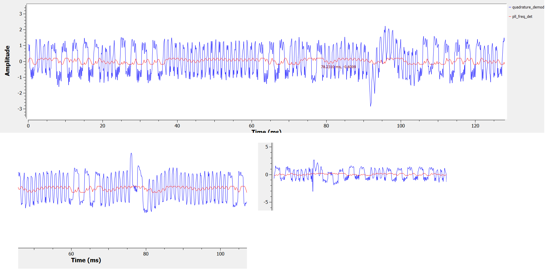
Example of what jitter i'm talking about, a specific configuration PLL freq det is in red, while quad demod (gain 1) is in blue
And this is the graph that used to take the screenshots

I Did tried, of course multiple configurations for the PLL.
Question time:
1. Am I doing something wrong? how can I extract the data that is obviously there and get the bits? sure there can be occasional noise but I tried multiple times to get a very clean capture and I wasn't able to,
2. Can the transition width (I.E. the `speed` of transition between high to low), the difference between high and low (FSK deviation) or other information could be Incorporated to enhance demodulation [both of which seems pretty much constant throughout transmission] ? How?
3. This is probably asked in the past, and I looked it up and wasn't able to come to a conclusion, How can I decode manchester in gnuradio?
The source, 8khz sample rate, 32 bit float I/Q captured,roughly centered is attached to this mail
Some extra information:
-I Only have access to trigger communication of the device.
-All captures taken from very close proximity (~10 cm) the device is intended to work over hundreds of meters outdoors
-I Have access to FCC docs, but since I don't live in the US, I'm not sure what actual "primary" freq of the device is. I might be picking up some sideband noise (if that's the proper definition, you know, when a signal also mirrors itself with decreasing attenuations across some wide band). The vendor is also able to configure the device freq, to some extent..
-Data looks like manchester encoding since there are no long lows or highs. also it starts off with a sync of high freq low freq "long" repeating, which under Manchester is 010101...
Thanks for the help
HLL.